A Fully Introduction to Capacitor Symbols

What is Capacitor?
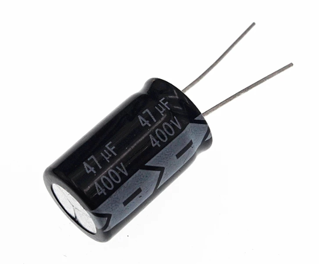
A capacitor is a passive electronic component that stores electrical energy in an electric field. It consists of two conductive plates separated by an insulating material called a dielectric. When a voltage is applied across the plates, an electric field develops, and charge is stored. Capacitors are fundamental components in various electronic circuits, playing crucial roles in filtering, energy storage, and signal coupling.
What is the Function of a Capacitor?
Capacitors are fundamental components in electronics with a variety of functions. Primarily, they store electrical energy when a voltage is applied across their terminals. This stored energy can be released when needed, making capacitors essential in power supply circuits to smooth voltage fluctuations and provide backup power.
Capacitors also play a critical role in filtering signals, where they can block direct current (DC) while allowing alternating current (AC) to pass, thus removing noise from the power supply lines. Additionally, capacitors are used in timing applications, such as in oscillators and timing circuits, where they determine the frequency of the oscillations. In coupling applications, capacitors connect different stages of circuits, enabling AC signals to pass while blocking DC components. This versatility makes capacitors indispensable in various electronic devices and systems.
What is the Capacitor Symbol Meaning?
The capacitor symbol in electronic schematics represents the component's functionality and type. The standard symbol for a non-polarized capacitor is two parallel lines, indicating the two conductive plates separated by the dielectric. This symbol highlights the capacitor’s ability to store energy between the plates.
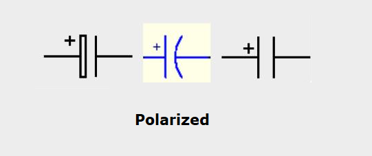
For polarized capacitors, such as electrolytic capacitors, the symbol includes a straight line (positive terminal) and a curved line (negative terminal), signifying the polarity. This distinction is crucial as incorrect polarity in an electrolytic capacitor can lead to malfunction or damage. Variable capacitors, which can adjust their capacitance, are represented by a standard capacitor symbol with an arrow across it, indicating the adjustable nature.
What are Types of Capacitor Symbols?
Classifying the circuit symbols of capacitors is essential for understanding their roles and ensuring proper use in electronic circuits. Here’s a detailed guide to help you recognize and classify different capacitor symbols.
Non-Polarized Capacitor Symbol
The non-polarized capacitor symbol consists of two parallel lines, representing a capacitor without a designated positive or negative terminal. These capacitors can be connected in any direction in the circuit and are typically used in AC applications, signal processing, and filtering where the direction of current flow changes periodically.

Polarized Capacitor Symbol
The polarized capacitor symbol includes one straight line (positive terminal) and one curved line (negative terminal). This indicates a capacitor with a specific polarity, such as an electrolytic capacitor. Polarized capacitors must be connected correctly according to their polarity to prevent damage or malfunction. They are commonly used in applications requiring large capacitance values, like power supplies and audio circuits.
Variable Capacitor Symbol
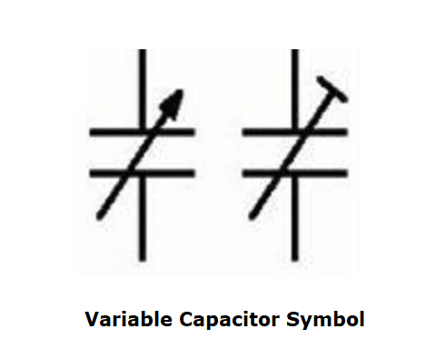
The variable capacitor symbol is depicted with a diagonal arrow across the standard capacitor symbol. This indicates a capacitor whose capacitance can be adjusted manually. Variable capacitors are used in applications where tuning is required, such as in radio frequency circuits, oscillators, and tuners. The adjustable nature of these capacitors allows for fine-tuning the circuit to achieve the desired performance.
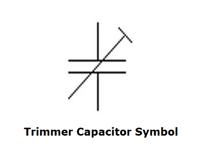
Trimmer Capacitor Symbol
The trimmer capacitor symbol is similar to the variable capacitor symbol but includes an additional line or screw symbol. This signifies a capacitor designed for fine-tuning and calibration purposes. Trimmer capacitors are typically used in precision applications where small adjustments are necessary, such as in communication equipment and RF circuits. They are often used for initial calibration and are not intended for frequent adjustment.
Specialty Capacitor Symbols
Polarized Tantalum Capacitor Symbol
The polarized tantalum capacitor symbol resembles the electrolytic capacitor symbol but may include a plus sign or arrow pointing to the positive terminal. Tantalum capacitors are known for their stability and high capacitance in a small package, making them suitable for space-constrained applications like mobile devices and automotive electronics. Correct polarity is crucial to avoid damage.
Supercapacitor Symbol
The supercapacitor symbol is typically depicted with a double line or a distinct marking to differentiate it from regular capacitors. Supercapacitors, also known as ultracapacitors, have much higher capacitance values than conventional capacitors and are used for energy storage applications, such as backup power supplies, energy harvesting, and regenerative braking systems. They can store and release energy rapidly, making them useful in high-power applications.
Feedthrough Capacitor Symbol
The feedthrough capacitor symbol includes a standard capacitor symbol with additional lines or arrows indicating its function as a pass-through device. Feedthrough capacitors are designed to filter high-frequency noise and are used in applications requiring electromagnetic interference (EMI) suppression, such as in power supply lines and shielding enclosures.
Motor Start Capacitor Symbol
The motor start capacitor symbol often includes a standard capacitor symbol with additional markings or labels indicating its use in motor start circuits. These capacitors provide the necessary phase shift to start single-phase induction motors, improving their starting torque and efficiency. They are commonly found in HVAC systems, compressors, and pumps.
Motor Run Capacitor Symbol
The motor run capacitor symbol is similar to the motor start capacitor symbol but indicates a capacitor used for continuous operation in motor circuits. Motor run capacitors improve the running efficiency and performance of motors, reducing energy consumption and extending motor life. They are used in fans, air conditioners, and other continuous-duty applications.
High Voltage Capacitor Symbol
The high voltage capacitor symbol includes additional markings or annotations indicating its ability to handle high voltage levels. These capacitors are used in applications where high voltage is present, such as in power transmission and distribution systems, medical equipment, and high-voltage power supplies. They are designed to withstand high electrical stress and provide reliable performance under extreme conditions.
What is the capacitor symbol on a multimeter?
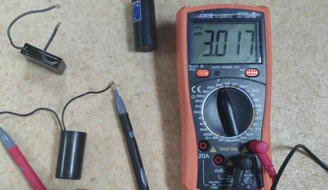
The capacitor symbol on a multimeter is typically represented by two parallel lines, one of which may be straight, and the other slightly curved or angled to indicate the plates of the capacitor. In some multimeters, especially those designed to measure polarized capacitors, the symbol might also include a small "+" sign near one of the lines to denote the positive terminal of an electrolytic capacitor. This visual representation helps users quickly identify the mode on the multimeter for measuring capacitance.
When you select the capacitor measurement mode on a multimeter, the device is set to measure the capacitance of a capacitor, typically displayed in farads (F), microfarads (µF), or picofarads (pF). This mode is used to determine the actual capacitance value of a capacitor, which can be crucial for verifying component specifications, diagnosing circuit issues, or ensuring that a capacitor is functioning correctly.
Using the Multimeter to Measure Capacitance
Capacitance is measured in farads, with most capacitors used in electronic circuits having values in the microfarad (µF) or picofarad (pF) range. Here's a quick reference for understanding capacitance values:
Farad (F): A large unit, rarely used for typical electronic components.
Microfarad (µF): Commonly used for capacitors in power supplies and audio circuits.
Nanofarad (nF): Used for filtering and signal coupling.
Picofarad (pF): Used in high-frequency and RF applications.
To measure the capacitance of a capacitor using a multimeter, follow these steps:
1. Power Off the Circuit
Powered circuit off and the capacitor is discharged to avoid damage to the multimeter and ensure safety.
2. Select the Capacitance Mode
Turn the dial on the multimeter to the capacitor symbol to select the capacitance measurement mode.
3. Connect the Leads
Connect the multimeter probes to the capacitor terminals. For non-polarized capacitors, the orientation does not matter. For polarized capacitors, connect the red probe to the positive terminal and the black probe to the negative terminal.
4. Read the Measurement
The multimeter will display the capacitance value on its screen. Compare this value to the capacitor's rated capacitance to determine if the component is within specifications.
Where is Capacitor Used?
Capacitors are everywhere in electronics and electrical systems. They perform crucial functions in various applications. Let's dive into where you can find capacitors and what they do.
Power Supply Systems
Capacitors play a key role in power supply systems. They smooth out the output voltage by filtering out ripples from rectified AC. This ensures you get a steady DC output, which is vital for the stable operation of your devices. They also store energy to provide power during short interruptions or surges, keeping everything running smoothly.
Signal Processing and Filtering
In signal processing, capacitors are your best friends. They filter out unwanted frequencies and noise, maintaining clean signals. When paired with resistors or inductors, they form filters that control the frequency range of signals. Plus, they decouple noise from power lines and keep your signals clean and clear.
Timing and Oscillation Circuits
Capacitors are essential in timing and oscillation circuits. They help determine the oscillation frequency and create precise time delays. In oscillators and timers, capacitors charge and discharge through resistors, setting the timing intervals needed for things like clocks and signal generators.
Coupling and Decoupling Applications
Capacitors are used in coupling and decoupling applications to connect AC signals between different amplifier stages while blocking DC components. This ensures the correct biasing conditions. They also isolate AC noise from DC power lines, keeping your power delivery stable.
Motor Start and Run Applications
In motors, capacitors provide the phase shifts needed to start single-phase induction motors and improve their running efficiency. Motor start capacitors boost starting torque, while motor run capacitors ensure efficient continuous operation in systems like HVAC and pumps.
Audio and Radio Frequency Applications
In audio and radio frequency (RF) circuits, capacitors are crucial. Variable capacitors adjust capacitance to select desired frequencies in radio tuners. Capacitors also couple audio signals between amplifier stages, maintaining signal fidelity and quality.

Energy Storage and Power Conditioning
Supercapacitors are amazing for energy storage and power conditioning. They store large amounts of energy and release it quickly, perfect for backup power supplies and electric vehicles. Capacitors also improve power factor in AC systems, reducing energy losses and boosting efficiency.
In addition to these applications, capacitors also used in our daily life like consumer electronics, medicals, digital electronics, automotives, and industrial equipment. They come in everywhere and every shape.
How to Read Capacitor Symbols?
Reading capacitor symbols correctly is crucial for interpreting circuit diagrams and using capacitors effectively. Here’s a streamlined guide to help you understand these symbols:
1. Understand the Units of Measurement
Capacitance is measured in F, but more commonly in μF, nF, due to practical component sizes. Knowing these units helps you accurately interpret the values.
2. Identify the Capacitance Value
The capacitance value is shown as a numerical digit on the symbol. Look for this number, which indicates the capacitance, often followed by a letter indicating the unit (e.g., μF, nF, pF).
3. Recognize the Tolerance Value
Capacitors have a tolerance value that shows the allowable deviation from the stated capacitance. This is usually represented by a percentage or a letter code on the symbol.
4. Note the Voltage Rating
The voltage rating indicates the maximum voltage the capacitor can safely handle. This is shown as a number followed by units like volts (V) or kilovolts (kV). For example, "25V" means the capacitor can handle up to 25 volts.
5. Check for Polarity
Polarized capacitors, such as electrolytic and tantalum capacitors, have a specific polarity and must be connected correctly. The symbol will include markings like a plus sign (+) or minus sign (-) to indicate the positive and negative terminals.
How to Distinguish the Positive and Negative Poles of Electrolytic Capacitors?
Properly identifying the positive and negative poles of electrolytic capacitors is crucial for their correct installation and operation. Here’s how you can distinguish between the two:
1. Check the Symbol on Circuit Diagrams
In circuit diagrams, the symbol for a polarized capacitor (like an electrolytic capacitor) will have a distinct marking to indicate polarity:
l The positive terminal is usually represented by a straight line.
l The negative terminal is often depicted by a curved line or a minus sign (-).
2. Look for Physical Markings on the Capacitor
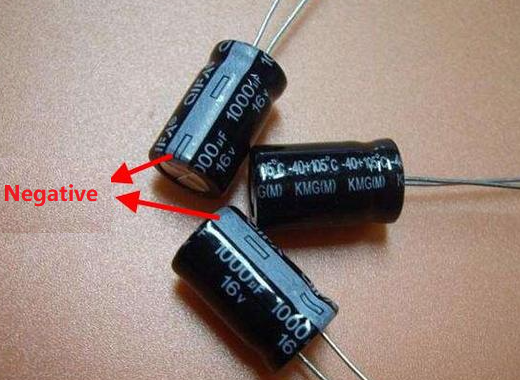
Electrolytic capacitors typically have clear markings on their bodies to indicate polarity:
l Positive Terminal (+): The positive lead is usually longer than the negative lead.
l Negative Terminal (-): The negative lead is often shorter and may have a stripe along
the side of the capacitor body. This stripe often contains minus signs (-) or other
indicators of the negative terminal.
3. Identify the Plus and Minus Signs
Manufacturers often print plus (+) and minus (-) signs directly on the capacitor to indicate the positive and negative terminals:
l A plus sign (+) near one lead indicates the positive terminal.
l A minus sign (-) near the other lead or a stripe on the body indicates the negative terminal.
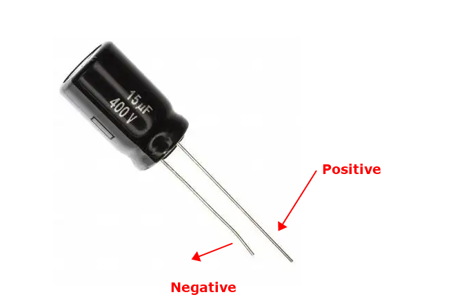
4. Observe the Lead Length
On new capacitors, the lead length can also be a clue:
l The longer lead is typically the positive terminal.
l The shorter lead is the negative terminal.
5. Use a Multimeter for Verification
If the markings are unclear, you can use a multimeter to check the capacitor:
1. Set the multimeter to the capacitance measurement mode.
2. Connect the multimeter probes to the capacitor leads.
3. A correct reading indicates proper connection; reverse the leads if you get a negative reading or if the multimeter displays an error.
FAQs About Capacitor Symbols
What does the basic capacitor symbol look like?
The basic capacitor symbol consists of two parallel lines. This represents a non-polarized capacitor, which can be connected in any direction within the circuit. For polarized capacitors, such as electrolytic capacitors, the symbol includes one straight line (positive terminal) and one curved line (negative terminal) to indicate the correct polarity.
How can I identify the capacitance value from the capacitor symbol?
Answer: The capacitance value is usually represented by numerical digits on the capacitor itself or in the circuit diagram near the symbol. This number indicates the capacitance, which is measured in Farads (F), microfarads (μF), nanofarads (nF), or picofarads (pF). For example, "100μF" indicates a capacitance of 100 microfarads.
What does the tolerance value on a
capacitor symbol mean?
The tolerance value specifies the permissible deviation from the stated capacitance value. It is typically represented by a percentage or a letter code near the capacitance value on the symbol. For instance, "104K" indicates a capacitance with a ±10% tolerance, where "K" represents the tolerance value.
How do I read the voltage rating on a capacitor symbol?
The voltage rating is the maximum voltage a capacitor can safely handle, indicated by a number followed by units such as volts (V) or kilovolts (kV). For example, "25V" means the capacitor can handle up to 25 volts. This rating is often marked on the capacitor itself or noted in the circuit diagram.
How can I tell the positive and negative terminals of a polarized capacitor from the symbol?
For polarized capacitors, such as electrolytic capacitors, the symbol includes specific markings to indicate polarity. The straight line represents the positive terminal, and the curved line or a line with a minus sign represents the negative terminal. On the capacitor body, the positive terminal may be indicated by a longer lead or a plus sign (+), while the negative terminal is often marked with a stripe or minus sign (-).
Statement
All articles (images, texts, audio) on this site are uploaded and shared by users, or integrated from relevant internet sources, only for user's learning. If your rights are violated, please contact the administrator to delete! Link to this article: https://www.jinftry.com

