A1015 Transistor Pinout, Equivalent & Datasheet

Introduction to A1015 Transistor
The A1015 transistor is a widely used PNP transistor known for its versatility in various electronic circuits. With its ability to handle low-power applications, it's a popular choice for amplification and switching tasks. Whether you're a beginner in electronics or a seasoned engineer, understanding the A1015 transistor's characteristics and uses can enhance your circuit designs.
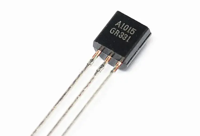
Specifications of A1015 Transistor
The A1015 transistor stands out due to its impressive features. It's designed to operate at low voltages, making it ideal for applications where power efficiency is crucial. The A1015 can handle a collector current of up to 150mA, which is suitable for small signal amplification.
l Type: PNP
l Collector-Base Voltage (VCBO): -50V
l Collector-Emitter Voltage (VCEO): -50V
l Emitter-Base Voltage (VEBO): -5V
l Collector Current (IC): -150mA
l Power Dissipation (PC): 400mW
l DC Current Gain (hFE): 70 to 400
l Transition Frequency (fT): 100MHz
Absolute Maximum Ratings (Ta = 25°C)
It's crucial to understand the absolute maximum ratings of the A1015 transistor to avoid damaging the component. Operating the transistor within these limits ensures reliability and longevity.
|
Characteristic |
Symbol |
Rating |
|
Collector-Base Voltage |
VCBO |
-50V |
|
Collector-Emitter Voltage |
VCEO |
-50V |
|
Emitter-Base Voltage |
VEBO |
-5V |
|
Collector Current |
IC |
-150mA |
|
Power Dissipation |
PC |
400mW |
|
Junction Temperature |
Tj |
150°C |
|
Storage Temperature |
Tstg |
-55°C to 150°C |
A1015 Pinout
The A1015 transistor has three pins: the emitter (E), the collector (C), and the base (B). Knowing the pinout is vital for correctly integrating the transistor into your circuit.
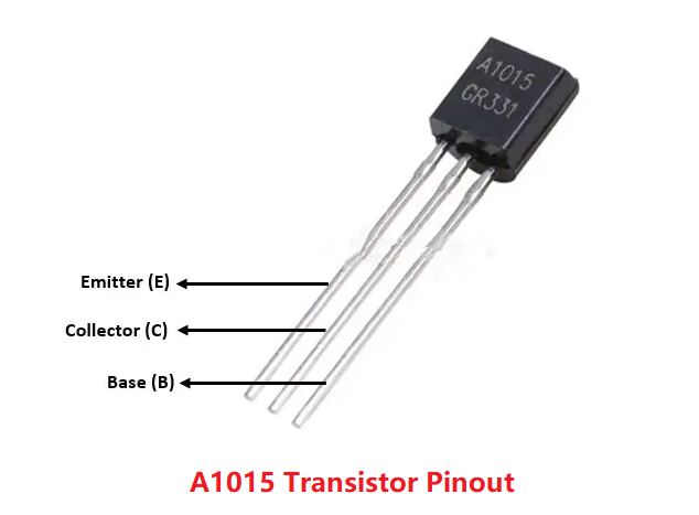
Pin 1: Emitter (E) - Connected to the negative side of the circuit.
Pin 2: Base (B) - Controls the transistor's operation.
Pin 3: Collector (C) - Connected to the load in the circuit.
A1015 Circuit Symbol
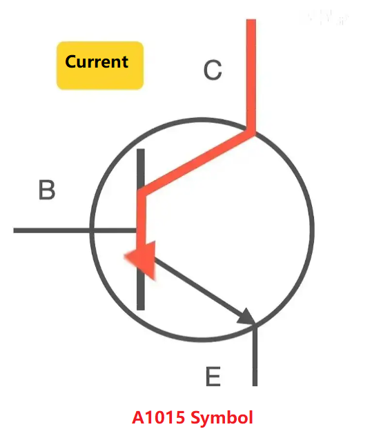
A1015 Transistor Circuit Diagram
In a typical circuit, the A1015 transistor is used in amplification mode. When a small current is applied to the base, it controls a larger current flow from the emitter to the collector.
Base: Connected to the input signal.
Emitter: Connected to the ground.
Collector: Connected to the load (such as a speaker or LED).
In the LED flasher circuit shown above, a 2SA1015 transistor is used to control the LED's flashing behavior.
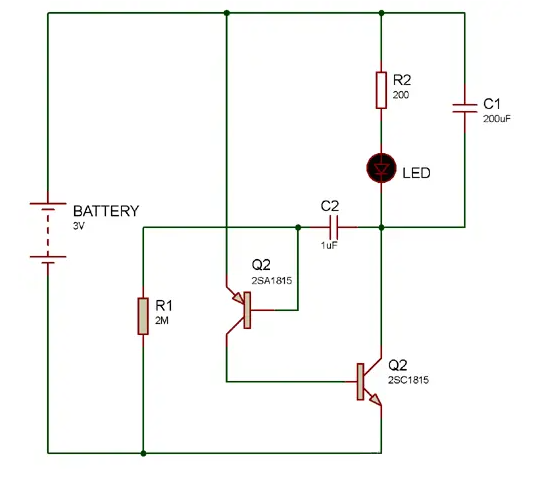
The circuit includes a capacitor (C1) and a resistor (R1) that work together to produce a specific frequency. This frequency is fed to the base of the transistor Q1, which acts as a switch controlling the second transistor, Q2. Q2 amplifies the current to drive the LED. Here's how it works:
1. Initially, voltage builds up across C1. During this time, Q1 remains active, allowing current to flow through R2 and the LED, causing the LED to light up.
2. As the voltage across C1 continues to increase, it eventually causes Q2 to start conducting. This further increases the current through the LED, making it glow brightly.
3. When C1 discharges through R1, the voltage drops to a level where it can no longer keep Q1 active. As a result, Q1 turns off, which also deactivates Q2. Consequently, the LED turns off.
With the LED off, C1 begins to charge again, and the cycle repeats. This on-off cycling creates the flashing effect of the LED.
A1015 Transistor 2D Model
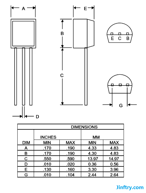
A1015 Transistor Uses
The A1015 transistor is used in various applications due to its reliability and efficiency in low-power circuits. Some common uses include:
1. Audio Amplification
The A1015 transistor is frequently used in audio amplification circuits. Its ability to handle low-frequency signals makes it ideal for enhancing audio output in devices like radios, portable speakers, and other audio equipment. In these applications, the transistor acts as a key component in amplifying weak audio signals to drive speakers or headphones, providing clear and louder sound.
2. Switching Applications
As a PNP transistor, the A1015 can function effectively as a switch in various electronic circuits. It’s used to control the flow of current to different parts of a circuit, enabling or disabling components like LEDs, relays, and other low-power devices. This switching capability is crucial in battery-powered devices, where efficient power management is essential.
3. Signal Processing
The A1015 transistor is also employed in signal processing circuits, where it helps to amplify or modify input signals. It’s often found in communication devices, where it processes signals to improve clarity and strength before transmission. In these circuits, the transistor’s role is critical in maintaining signal integrity and ensuring that the transmitted or received signal is strong enough to be processed by subsequent stages.
4. Oscillator Circuits
In oscillator circuits, the A1015 transistor is used to generate repetitive signals, such as square waves or sine waves. These signals are fundamental in applications like timers, waveform generators, and clock circuits. The transistor’s ability to operate at different frequencies makes it a reliable component in these circuits, ensuring stable and accurate signal generation.
5. Voltage Regulation
The A1015 transistor is sometimes used in voltage regulation circuits, where it helps maintain a steady output voltage despite variations in the input voltage or load conditions. This is crucial in power supply circuits, where consistent voltage is necessary to ensure the reliable operation of electronic devices. The transistor can be part of a regulator circuit that adjusts the voltage to desired levels, protecting sensitive components from voltage fluctuations.
6. Current Limiting Circuits
In current limiting circuits, the A1015 transistor is used to prevent excessive current from flowing through a circuit, which could potentially damage components. By limiting the current to a safe level, the transistor helps protect the circuit from overcurrent conditions, enhancing the reliability and longevity of the electronic device.
7. Sensor Interface
The A1015 transistor is also used in interfacing sensors with microcontrollers or other digital logic circuits. It can amplify the small signals generated by sensors, such as temperature or light sensors, to a level that can be processed by digital circuits. This application is common in automation systems, where sensors play a crucial role in monitoring and controlling various parameters.
8. Push-Pull Amplifiers
In push-pull amplifier configurations, the A1015 transistor is used alongside its complementary NPN transistor (like the C1815) to amplify signals with higher efficiency. This setup is commonly used in power amplification stages of audio equipment, where the push-pull configuration helps reduce distortion and improve power output.
9. Darlington Pair Configuration
The A1015 can be used in a Darlington pair configuration to achieve a higher current gain. This is useful in applications where a small input current needs to control a much larger load. In this setup, the A1015 works in tandem with another transistor to amplify the input signal significantly, making it suitable for driving larger loads in electronic circuits.
10. Analog Circuitry
In analog circuits, the A1015 transistor is used for tasks like signal mixing, filtering, and modulation. Its ability to handle analog signals makes it an essential component in circuits that require precise control over signal amplitude and frequency. These applications are common in communication systems, where analog signals are still widely used.
What is the Alternative of A1015 Transistor?
When the A1015 transistor is unavailable, several alternatives can be used. The 2N2907 and BC557 are popular PNP transistors with similar specifications. Below we listing some other alternatives of A1015 transistor and their basic specifications.
|
Transistor |
Manufacturer |
Type |
VCEO (Collector-Emitter Voltage) |
IC (Collector Current) |
hFE (DC Current Gain) |
|
2N2907 |
Fairchild |
PNP |
-60V |
-800mA |
100 to 300 |
|
BC557 |
Philips |
PNP |
-45V |
-100mA |
125 to 800 |
|
S8550 |
Samsung |
PNP |
-25V |
-500mA |
120 to 400 |
|
2SA1015 |
Toshiba |
PNP |
-50V |
-150mA |
70 to 400 |
|
2SA733 |
Toshiba |
PNP |
-50V |
-150mA |
120 to 400 |
|
KSA1015 |
ON Semiconductor |
PNP |
-50V |
-150mA |
70 to 400 |
|
2SA872 |
NEC |
PNP |
-60V |
-800mA |
100 to 320 |
|
BC327 |
ON Semiconductor |
PNP |
-45V |
-800mA |
160 to 630 |
|
2SA1775 |
Toshiba |
PNP |
-50V |
-200mA |
100 to 630 |
|
2SA564 |
NEC |
PNP |
-50V |
-100mA |
110 to 800 |
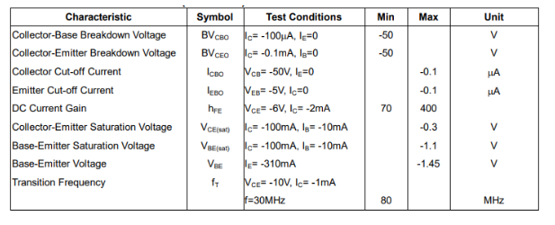
Electrical Characteristics
The electrical characteristics of the A1015 transistor define how it behaves under different conditions:
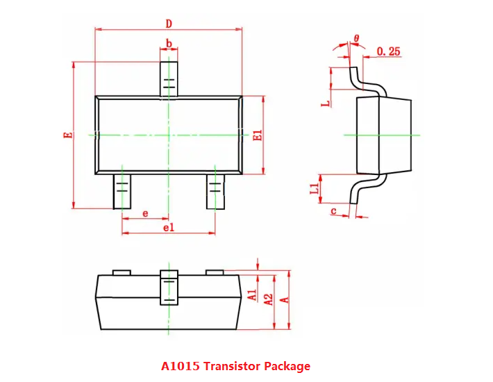
A1015 Package
The A1015 transistor is typically available in the TO-92 package, a compact and commonly used package for small transistors. Its small size allows it to fit easily into densely packed circuit boards.
What is the Complementary Transistor of A1015?
The complementary transistor to the A1015 is the C1815, an NPN transistor with similar characteristics. The C1815 is often used in circuits where both PNP and NPN transistors are required, such as in push-pull amplifiers.
C1815 Transistor Overview:
Type: NPN
VCEO (Collector-Emitter Voltage): 50V
IC (Collector Current): 150mA
hFE (DC Current Gain): 70 to 240
Package: TO-92
In circuits, the A1015 (PNP) and C1815 (NPN) are often used together in push-pull amplifier configurations and other designs where both types of transistors are needed for efficient signal amplification and switching.
What is the Voltage of A1015?
The A1015 transistor can handle a collector-emitter voltage of up to -50V. This makes it suitable for low to medium voltage applications, ensuring stable operation within its specified limits.
How to Use A1015 Transistor?
Using the A1015 transistor in your circuit involves connecting the emitter to the ground, the base to the input signal through a resistor, and the collector to the load. By controlling the base current, you can efficiently switch or amplify signals.
For instance, in an amplifier circuit:
Step 1: Connect the emitter to ground.
Step 2: Apply the input signal to the base.
Step 3: Connect the collector to the load.
This simple setup allows the A1015 to amplify small signals, making it a versatile component in various electronic designs.
FAQs about A1015 Transistor
1. How do I use the A1015 transistor in an amplifier circuit?
For amplification, set up a biasing network to keep the transistor in its active region. Apply the input signal to the base through a coupling capacitor, and connect the output to the collector. The transistor will amplify the input signal according to its gain characteristics.
2. What is the maximum voltage that the A1015 transistor can handle?
The A1015 can handle a maximum collector-emitter voltage (VCEO) of -50V. Exceeding this voltage could damage the transistor.
3. What is the maximum collector current for the A1015 transistor?
The A1015 can handle a maximum collector current (IC) of -150mA. Ensure that the current through the transistor does not exceed this limit to avoid damage.
4. What is the typical gain of the A1015 transistor?
The DC current gain (hFE) of the A1015 typically ranges from 70 to 400, depending on the specific transistor and its operating conditions.
5. How should I choose the base resistor for the A1015 transistor?
The base resistor should be chosen to provide sufficient base current to ensure that the transistor operates properly in its active or saturation region. Calculate the base resistor value based on the desired collector current and the transistor’s current gain.
6. Can the A1015 transistor be used in a Darlington pair configuration?
Yes, the A1015 can be used in a Darlington pair configuration to achieve higher current gain. In this setup, the A1015 is paired with another transistor, with its base connected to the collector of the second transistor.
Statement
All articles (images, texts, audio) on this site are uploaded and shared by users, or integrated from relevant internet sources, only for user's learning. If your rights are violated, please contact the administrator to delete! Link to this article: https://www.jinftry.com


