Previous Chapter:IC 7490 Decade Counter: Pin Diagram, Working & Features
Next Chapter:What is a USB Connector? And It's Working Principle?
How to Combine Non Nonpolar Capacitors: The Ultimate Guide

Post Date:2024-08-09,

What is a non-polarized capacitor?
Non-polarized capacitors, also known as non-polarized capacitors, are capacitors that can be used in circuits without being restricted by positive or negative polarity. This means that they can be connected in any direction in a circuit without affecting their function or causing damage. Nonpolar capacitors are designed so that there is no fixed polarity between their two electrodes, thanks to the dielectric material they use.Construction and materials of non-polar capacitors
They usually consist of two layers of metal foil or film as electrodes separated by a dielectric material. The dielectric can be ceramic, polyester, polypropylene, mica, glass and other materials.Operating Principle of Nonpolar Capacitors
The basic principle of operation of a capacitor involves the storage of charge. A capacitor consists of two conductors (electrodes) which are separated by an insulating material (dielectric). When a voltage is applied to the two electrodes of a capacitor, charge builds up on the electrodes, creating an electric field across the dielectric. This process actually creates a charge distribution in the dielectric, which stores energy.In the case of non-polar capacitors, the dielectric is typically unpolarized, or if polarized, it is so slight that it does not cause a noticeable difference in performance over the normal range of use of the capacitor. This characteristic allows non-polarized capacitors to withstand forward or reverse voltages in circuits without performance degradation or damage due to misdirection of polarization, as is the case with polarized capacitors.
Characteristics of non-polarized capacitors
- Bi-directional use: Due to their lack of polarity, non-polarized capacitors can be used in both AC and DC circuits with no need to consider positive or negative connections.
- High stability: Non-polar capacitors show good stability in temperature and frequency changes.
- Low loss: Many non-polar capacitors have a low loss factor and are suitable for high frequency circuits.
Application of non-polar capacitors
- Filtering and decoupling: Commonly used in power supply circuits for filtering and decoupling to reduce noise and interference.
- Signal coupling and bypass: Used in amplifiers and signal processing circuits for coupling and bypass.
- Oscillation Circuit: Used in oscillation circuits to stabilize frequency.
- Energy storage: In some applications that require fast charging and discharging, such as flash circuits.
Common types of non-polarized capacitors
- Ceramic Capacitors: For high frequency circuits with stable capacitance values and good temperature stability.
- Polyester (PET) Capacitors: Low cost, suitable for audio and power bypass applications.
- Polypropylene (PP) capacitors: excellent frequency characteristics, suitable for audio and power electronics.
- Mica Capacitors: Very low loss and high stability, suitable for precision instruments and RF circuits
Symbols for non-polar capacitors

Polarized capacitor symbol

How to combine non-polar capacitors
The method of combining non-polar capacitors depends mainly on the circuit function you want to realize and the characteristics of the capacitors. Non-polar capacitors, such as ceramic capacitors and film capacitors, have no positive or negative polarity and can be connected at will. Here are a few common ways to combine them:Series-connected capacitors
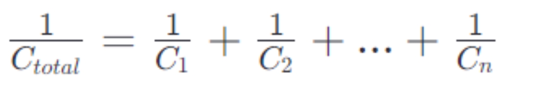
When capacitors are connected in series, their total capacitance decreases. This is because series connection increases the total thickness of the dielectric, which reduces the capacitance value. Total capacitance
Total capacitance
Step:
- Connect the capacitors head to tail.
- Calculate the total capacitance, making sure not to exceed the maximum value required by the circuit.
- Note that the withstand voltages of series capacitors are additive, so you can increase the voltage withstand capability of the entire circuit.
Connecting Capacitors in Parallel
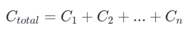
When connecting capacitors in parallel, the total capacitance increases because it is equivalent to increasing the effective area of the capacitors. The total capacitance is simply equal to the sum of the capacitance values of the individual capacitors:
Step:
- Connect the positive and negative terminals of all capacitors together.
- Make sure that the withstand voltage of the parallel capacitors matches at least the highest voltage in the circuit.
Practical steps for combining non-polar capacitors
1. Determine the needs: Select the appropriate way of combining capacitors (series, parallel or mixed) according to the needs of the circuit.2. Selection of capacitors: Select the appropriate capacitor according to the required capacitance and voltage withstand value. Make sure that the rated voltage of the capacitor can meet the requirements of the circuit.
3. Connect the capacitors:
- Series connection: Connect one pin of a capacitor to the pin of another capacitor to form a continuous path.
- Parallel connection: connect both ends of the capacitor to the same node respectively.
- Mixed connection: Connect some capacitors in series and some in parallel according to specific needs.
5. Test: Test the effect of the capacitor combination in the actual circuit to ensure that it meets the expected performance requirements.
Connection Precautions:
- Withstanding voltage value: series connection can increase the withstanding voltage value, parallel connection cannot.
- Capacitance: Connecting in parallel increases the capacitance, connecting in series decreases it.
- Losses and ESR: Capacitor losses and Equivalent Series Resistance (ESR) also affect circuit performance, especially in high frequency circuits.
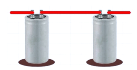
Circuit diagram of series connection of electrolytic capacitors to form non-polar capacitors

How to charge a non-polarized capacitor?
The process of charging a non-polarized capacitor is relatively straightforward because these types of capacitors do not have fixed positive and negative terminals, so you can use any type of direct current (DC) power supply for charging.Charging Steps:
- PREPARE THE POWER SUPPLY: First, you will need a DC power supply, which can be a battery, power adapter, or lab power supply. The voltage of the power supply should be lower or equal to the rated voltage of the capacitors to avoid over-voltage damage to the capacitors.
- Connecting the Capacitor: Connect each end of the capacitor to the positive and negative terminals of the power supply. Since there is no positive or negative terminal for non-polarized capacitors, theoretically, you can connect them as many times as you like, but it is recommended to keep them consistent for the sake of circuit consistency and to avoid confusion.
- CLOSED CIRCUIT: Once connected and the circuit is closed (if there is a switch in the circuit), the capacitor will begin to charge. During the charging process, the capacitor accumulates charge until its voltage is equal to the supply voltage.
- Monitor the charging process: You can use a voltmeter or oscilloscope to monitor the voltage across the capacitor to determine when it is fully charged. Charging is complete when the capacitor's voltage reaches the supply voltage.
- Disconnect the circuit: Once the capacitor is fully charged, disconnect the power supply to stop the charging process. At this point, the energy stored in the capacitor can be used for subsequent operations in the circuit, such as discharging to a load or for timing circuits.
What are the advantages of non-polarized capacitors?
No polarity limitations:Non-polarized capacitors can be connected in any direction without regard to positive or negative polarity. This makes them more flexible in circuit design and application.
High stability:
Nonpolar capacitors show better stability when temperature and frequency change. For example, ceramic and film capacitors show less change in capacitance when the temperature changes.
Low loss:
Many non-polar capacitors have low loss factors (DF) and are suitable for high frequency circuits. For example, film and ceramic capacitors exhibit low losses at high frequencies.
High insulation resistance:
Nonpolar capacitors typically have high insulation resistance and can hold a charge for long periods of time without leakage. This makes them suitable for applications that require high stability and long life.
Small size and light weight:
Many non-polar capacitors, such as ceramic capacitors, are small in size and light in weight, making them suitable for miniaturized and high-density mounting of electronic equipment.
Wide Operating Voltage Range:
Non-polar capacitors typically have a wide operating voltage range, making them suitable for applications in a variety of voltage conditions.
Fast Charge and Discharge Capability:
Non-polar capacitors, such as film capacitors and ultracapacitors, have fast charge and discharge capabilities for applications that require rapid energy release, such as flash lamps and power tools.
Long Life:
Non-polar capacitors (especially film capacitors) have a long life span and maintain good performance even under harsh operating conditions.
Environmentally friendly materials:
Many non-polar capacitors (such as ceramic and film capacitors) are made from environmentally friendly materials and comply with environmental standards such as RoHS.
How to create non-polar capacitors from polar capacitors?
1. Check the capacitor. One side of the capacitor has a polarity marking, such as a minus sign. One lead may be shorter than the other; if this is seen, the shorter lead is negative.2. Solder the negative leads of both capacitors together so that the positive lead hangs in the air.
3. Turn the function knob of the multimeter to the capacitor setting. Touch the tip of the multimeter probe to the capacitor leads. Each lead should be connected to one probe tip; do not short the leads together. Observe a reading of approximately 50 microfarads on the multimeter display. Two capacitors of the same value are connected in series with a total capacitance of half the original value.
This is shown in the diagram below:

Conclusion
The key when combining non-polarized capacitors is to understand the fundamentals of capacitance and how to adjust capacitance values by connecting in series and parallel. With careful planning and accurate execution, you can build a capacitor combination that meets the needs of your circuit. Always follow safety procedures, especially when working with high-voltage capacitors.Statement
All articles (images, texts, audio) on this site are uploaded and shared by users, or integrated from relevant internet sources, only for user's learning If your rights are violated, please contact the administrator to delete! Link to this article: https://www.jinftry.com/
Previous Chapter:IC 7490 Decade Counter: Pin Diagram, Working & Features
Next Chapter:What is a USB Connector? And It's Working Principle?


