Op Amp IC 741 Basics, Characteristics, Pins & Applications

The 741 operational amplifier (op-amp) IC is a fundamental building block in electronics. Known for its versatility and reliability, the 741 IC has become a staple in various analog signal processing tasks. This blog delves into the basics of the 741 op-amp, its pin configuration, key parameters, and practical applications. Whether you're a hobbyist or a professional, understanding the 741 IC will enhance your electronic circuit design skills.
What is the 741 Op Amp IC?
The 741 op-amp is a general-purpose operational amplifier integrated circuit. It was first introduced by Fairchild Semiconductor in the late 1960s. The 741 IC is widely used in analog electronics due to its stable performance and ease of use. It is encapsulated in an 8-pin dual in-line package (DIP), making it suitable for breadboard prototyping and PCB applications.

Key Features of the 741 Op Amp IC
1. high open-loop gain
2. wide input voltage range
3. dual power supply operation
4. moderate slew rate
5. high input impedance
6. low output impedance
7. low input offset voltage
8. common-mode rejection ratio (CMRR)
9. power supply rejection ratio (PSRR)
10. versatile package options
Specifications of 741 Op Amp
The following table summarizes the key specifications of the 741 operational amplifier (op-amp):
|
Parameter |
Specification |
|
Open-Loop Gain (A_OL) |
200,000 (106 dB) |
|
Gain Bandwidth Product (GBP) |
1 MHz |
|
Input Offset Voltage (V_os) |
Typically 2 mV |
|
Input Bias Current (I_b) |
Typically 80 nA |
|
Input Impedance (Z_in) |
Typically 2 MΩ |
|
Output Impedance (Z_out) |
Typically 75 Ω |
|
Slew Rate (SR) |
0.5 V/µs |
|
Common-Mode Rejection Ratio (CMRR) |
90 dB |
|
Power Supply Rejection Ratio (PSRR) |
100 dB |
|
Input Voltage Range (V_in range) |
±12V with ±15V power supply |
|
Output Voltage Swing (V_out swing) |
±12V with ±15V power supply |
|
Supply Voltage (V_s) |
±15V typical (dual supply) |
|
Total Harmonic Distortion (THD) |
0.003% at 1 kHz |
|
Noise Density |
20 nV/√Hz |
|
Operating Temperature Range |
0°C to +70°C |
|
Package Types |
8-pin DIP, SOIC |
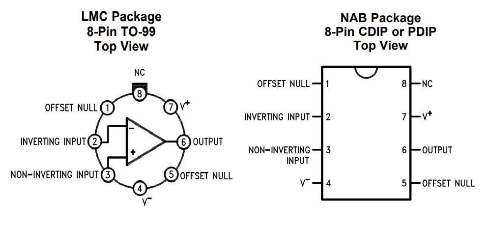
Pinout of IC 741 Op Amp and Their Functions
The 741 operational amplifier (op-amp) IC is encapsulated in an 8-pin dual in-line package (DIP). Each pin has a specific function crucial to the operation of the op-amp. Below is a detailed description of the pin configuration and their respective functions with different packages:

Pin Descriptions
1. Offset Null (Pin 1 and Pin 5):
Used for offset nulling. The offset null adjustment is required to minimize the offset voltage at the output. This is achieved by connecting a potentiometer between these two pins and adjusting it to zero the offset voltage.
2. Inverting Input (Pin 2):
The inverting input of the op-amp. A signal applied to this pin is amplified and inverted at the output. In an inverting amplifier configuration, the input signal is fed into this pin through a resistor.
3. Non-Inverting Input (Pin 3):
The non-inverting input of the op-amp. A signal applied to this pin is amplified without inversion at the output. This pin is used in non-inverting amplifier configurations.
4. V- (Negative Power Supply) (Pin 4):
The negative power supply pin. It is connected to the negative supply voltage (Vee). For typical operation, this is -15V.
5. Output (Pin 6):
The output of the op-amp. The amplified signal is available at this pin. This pin is connected to the load or to the next stage of the circuit.
6. V+ (Positive Power Supply) (Pin 7):
The positive power supply pin. It is connected to the positive supply voltage (Vcc). For typical operation, this is +15V.
7. NC (No Connection) (Pin 8):
Not connected internally and is used for mechanical support only. It has no electrical function.
How Does 741 IC Work?
The 741 op-amp operates by amplifying the voltage difference between its inverting (-) and non-inverting (+) inputs. The output voltage is given by the formula:

Where Vout is the output voltage, Aol is the open-loop gain (typically around 200,000 for the 741), V+ is the voltage at the non-inverting input (Pin 3), and V- is the voltage at the inverting input (Pin 2).
Feedback Mechanism
The behavior of the 741 op-amp in practical circuits is often controlled using negative feedback. Feedback is the process of feeding a portion of the output signal back to the input. There are two common feedback configurations:
1. Inverting Amplifier Configuration
In this configuration, the input signal is applied to the inverting input (Pin 2) through a resistor Rin and the non-inverting input (Pin 3) is grounded. A feedback resistor Rf is connected between the output (Pin 6) and the inverting input (Pin 2). The gain of the inverting amplifier is given by the formula:

The negative sign indicates that the output is inverted relative to the input.
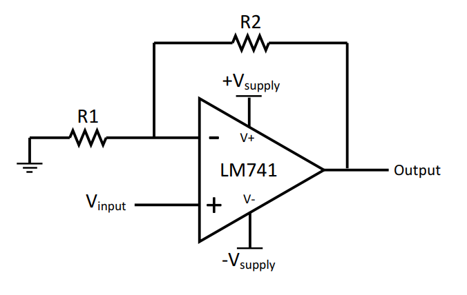
2. Non-Inverting Amplifier Configuration
In this configuration, the input signal is applied to the non-inverting input (Pin 3), and the inverting input (Pin 2) is connected to a voltage divider formed by resistors R1 and R2. The output (Pin 6) is fed back to the inverting input through resistor R2, while R1 is connected between the inverting input and ground. The gain of the non-inverting amplifier is given by the formula:

Here is the circuit diagram of a non-inverting amplifier using 741 IC.

What is an Alternative to Opamp 741 IC?
While the 741 op-amp is versatile, there are alternatives that offer different features or improved performance. One popular alternative is the LM358 dual op-amp. The LM358 consists of two independent, high-gain, internally frequency-compensated operational amplifiers. Unlike the 741, the LM358 can operate on a single power supply, making it ideal for battery-operated circuits.
|
Op-Amp |
Packages |
Power Supply |
Typical Size (DIP / SOIC) |
|
LM358 |
8-pin DIP, SOIC, TSSOP |
Single supply (3V to 32V) |
8.6 mm x 3.9 mm / 4.9 mm x 3.9 mm |
|
LM324 |
14-pin DIP, SOIC, TSSOP |
Single supply (3V to 32V) |
19.3 mm x 6.35 mm / 8.65 mm x 3.91 mm |
|
TL081 |
8-pin DIP, SOIC |
Dual supply (±3V to ±18V) |
8.6 mm x 3.9 mm / 4.9 mm x 3.9 mm |
|
NE5532 |
8-pin DIP, SOIC |
Dual supply (±3V to ±20V) |
8.6 mm x 3.9 mm / 4.9 mm x 3.9 mm |
|
OPA2134 |
8-pin DIP, SOIC, TSSOP |
Dual supply (±2.5V to ±18V) |
8.6 mm x 3.9 mm / 4.9 mm x 3.9 mm / 3.0 mm x 3.0 mm |
|
MC1458 |
8-pin DIP, SOIC |
Dual supply (±3V to ±18V) |
8.6 mm x 3.9 mm / 4.9 mm x 3.9 mm |
|
LF353 |
8-pin DIP, SOIC |
Dual supply (±3V to ±18V) |
8.6 mm x 3.9 mm / 4.9 mm x 3.9 mm |
|
OP07 |
8-pin DIP, SOIC |
Dual supply (±3V to ±18V) |
8.6 mm x 3.9 mm / 4.9 mm x 3.9 mm |
These alternatives to the 741 op-amp provide a range of options for different applications, offering various package types, power supply requirements, and sizes to suit specific design needs.
Summary Dimensions and Size of IC 741
The 741 operational amplifier (op-amp) is commonly packaged in an 8-pin Dual In-line Package (DIP) or Small Outline Integrated Circuit (SOIC). The dimension of 741 IC differs in different packages. Below are the typical dimensions and sizes for these packages:
8-Pin DIP Package
Length: 9.27 mm (0.365 inches)
Width: 6.35 mm (0.25 inches)
Height: 4.57 mm (0.18 inches)
Pin Spacing (Pitch): 2.54 mm (0.1 inches) between pins
Row Spacing: 7.62 mm (0.3 inches) between rows of pins
8-Pin SOIC Package
Length: 4.9 mm (0.193 inches)
Width: 3.9 mm (0.154 inches)
Height: 1.75 mm (0.069 inches)
Pin Spacing (Pitch): 1.27 mm (0.05 inches) between pins
Row Spacing: 3.8 mm (0.15 inches) between rows of pins
What is the Difference Between IC 741 and LM358?
The 741 and LM358 operational amplifiers serve similar purposes but have distinct characteristics that make them suitable for different applications. Here is a summary of LM358 part.
l Power Supply Requirements
The 741 requires a dual power supply (±15V), whereas the LM358 can operate on a single power supply (3V to 32V), making it more versatile for battery-operated and single-supply applications.
l Input Characteristics
The LM358 has lower input bias current (20 nA) compared to the 741 (80 nA), making it more suitable for precision applications.
l Output Characteristics
Both op-amps have similar gain bandwidth products (1 MHz), but the 741 has a slightly higher slew rate (0.5 V/µs) compared to the LM358 (0.3 V/µs).
l Operating Temperature Range
The LM358 operates over a wider temperature range (-40°C to +85°C), making it suitable for industrial and automotive applications, while the 741 operates from 0°C to +70°C.
l Output Voltage Swing
The LM358 can achieve rail-to-rail output with a single supply, which is advantageous for low-voltage applications, while the 741 offers a wider output swing with dual supplies.
LM358 operational amplifier (op-amp) specification
|
Parameter |
Specification |
|
Power Supply Requirements |
Single power supply: 3V to 32V |
|
Input Offset Voltage |
Typically 2mV |
|
Input Bias Current |
Approximately 20nA |
|
Input Impedance |
High, similar to 741 |
|
Output Impedance |
Low, suitable for driving loads |
|
Slew Rate |
0.3 V/µs |
|
Gain Bandwidth Product (GBP) |
1 MHz |
|
Common-Mode Rejection Ratio (CMRR) |
Similar to 741 |
|
Power Supply Rejection Ratio (PSRR) |
Similar to 741 |
|
Operating Temperature Range |
-40°C to +85°C |
|
Output Voltage Swing |
Rail-to-rail with single supply |
|
Package Types |
8-pin DIP, SOIC, and surface-mount |
Why Does IC741 Require Both +15Vcc & -15Vee?
The 741 op-amp requires a dual power supply to handle both positive and negative input signals effectively. This dual supply allows the output to swing both above and below the ground (0V), enabling a wider range of analog signal processing. It has two benefits:
1. Increased Output Range - the output can swing more positively and negatively, enhancing signal amplification.
2. Improved Signal Processing - allows for the handling of AC signals and more complex waveform operations.
In many modern applications, dual power supplies are readily available, making the 741 a viable choice. However, for single-supply environments, the LM358 or similar op-amps might be more suitable.
What is IC 741 Used For?
The 741 operational amplifier (op-amp) is one of the most versatile and widely used components in analog electronics. Its broad range of applications stems from its ability to amplify weak electrical signals, perform mathematical operations, generate waveforms, and condition signals. Here are some detailed uses of the IC 741:
Signal Amplification
The primary function of the 741 op-amp is to amplify signals. It can amplify both AC and DC signals, making it suitable for a variety of applications, including audio equipment, sensor signal conditioning, and data acquisition systems. In an inverting or non-inverting amplifier configuration, the 741 can provide precise and stable gain, essential for processing small voltage signals from sensors or microphones.
Analog Computation
The 741 op-amp can be used to perform analog computations such as addition, subtraction, integration, and differentiation. These operations are crucial in analog computers and signal processing applications. For example, in an integrator circuit, the 741 can compute the integral of an input signal, which is useful in applications like signal integration in control systems or waveform generation.
Oscillators
Oscillator circuits generate periodic waveforms such as sine, square, and triangular waves. The 741 op-amp is commonly used in oscillator designs due to its stable performance and ease of use. These oscillators are employed in various applications, including function generators, clock generators, and audio tone generation.
Filters
The 741 op-amp is used in the design of active filters, including low-pass, high-pass, band-pass, and band-stop filters. These filters are essential in signal conditioning applications where unwanted frequencies need to be attenuated, and desired signal components need to be passed. For example, a low-pass filter designed with a 741 op-amp can remove high-frequency noise from a sensor signal, improving the signal-to-noise ratio.
Comparators
Although not ideal due to its slower response time compared to dedicated comparators, the 741 op-amp can still be used as a comparator in less demanding applications. In comparator circuits, the 741 op-amp compares two input voltages and outputs a signal indicating which input is higher. This function is useful in applications such as zero-crossing detectors, level shifters, and analog-to-digital converters.
Gain vs. Frequency Characteristics
The gain vs. frequency characteristic of the 741 operational amplifier (op-amp) is a key parameter that defines its performance in various applications. This characteristic determines how the gain of the op-amp decreases with increasing frequency. Understanding this relationship helps in designing circuits that can operate effectively within the desired frequency range.
Open-Loop Gain
The open-loop gain of an op-amp is the gain without any feedback applied. For the 741 op-amp, the open-loop gain (A_OL) is typically very high, around 200,000 (or 106 dB) at low frequencies. However, this gain is not constant and decreases with increasing frequency.
Gain Bandwidth Product (GBP)
The Gain Bandwidth Product (GBP) is a constant parameter that represents the product of the gain and the bandwidth at which the gain becomes unity (1). For the 741 op-amp, the GBP is typically 1 MHz. This means that at a frequency of 1 MHz, the gain of the op-amp is 1.
Frequency Response
The frequency response of the 741 op-amp can be visualized through a Bode plot, which shows the gain in decibels (dB) versus the frequency in a logarithmic scale.
1. Low-Frequency Range:
- At low frequencies, the 741 op-amp exhibits its maximum open-loop gain (A_OL).
- The gain remains relatively flat and constant.
2. Mid-Frequency Range:
- As the frequency increases, the gain begins to decrease.
- This decrease follows a predictable slope, typically -20 dB/decade (a tenfold increase in frequency results in a tenfold decrease in gain).
3. High-Frequency Range:
- At high frequencies, the gain continues to decrease, eventually reaching unity gain (0 dB) at the frequency equal to the GBP.
- Beyond this point, the gain drops below unity, and the op-amp can no longer provide significant amplification.
Frequently Asked Questions (FAQs)
1. What are the key differences between the 741 op-amp and its alternatives like LM358 and TL081?
The 741 op-amp is a general-purpose amplifier with a high open-loop gain, moderate slew rate, and dual power supply requirements. Alternatives like the LM358 can operate on a single power supply, making them suitable for battery-powered applications. The TL081, on the other hand, offers higher input impedance and a higher slew rate, making it ideal for high-speed and high-fidelity applications. Each alternative has unique features that cater to specific needs, such as lower input offset voltage, lower input bias current, or extended temperature ranges.
2. Why would I choose an LM358 over a 741 op-amp?
You might choose an LM358 over a 741 op-amp if you need an operational amplifier that can operate on a single power supply (3V to 32V) and has a lower input bias current (approximately 20 nA). The LM358 is also suitable for applications that require operation over a wider temperature range (-40°C to +85°C), making it more versatile for battery-operated and outdoor applications.
3. What applications are best suited for the NE5532 op-amp?
The NE5532 op-amp is best suited for audio applications due to its low noise (approximately 5 nV/√Hz), low total harmonic distortion (THD), and high output drive capability. It is commonly used in high-fidelity audio equipment, mixers, preamplifiers, and other applications where audio quality and signal integrity are critical.
4. Can I use the OPA2134 in place of a 741 op-amp for audio applications?
Yes, the OPA2134 is a high-performance audio op-amp that can be used in place of a 741 for audio applications. It offers very low distortion, low noise, and a wide gain bandwidth product (8 MHz), making it ideal for professional audio equipment, mixers, and audio preamplifiers. Its performance characteristics make it superior to the 741 in audio applications.
5. What should I consider when selecting an op-amp for precision instrumentation?
When selecting an op-amp for precision instrumentation, consider factors such as input offset voltage, input bias current, common-mode rejection ratio (CMRR), and power supply rejection ratio (PSRR). Op-amps like the OP07, which offer ultra-low input offset voltage (75 µV), low input bias current (1 nA), high CMRR (114 dB), and low noise, are ideal for precision applications. These parameters ensure minimal error and high accuracy in low-level signal processing.
Statement
All articles (images, texts, audio) on this site are uploaded and shared by users, or integrated from relevant internet sources, only for user's learning. If your rights are violated, please contact the administrator to delete! Link to this article: https://www.jinftry.com


