Potentiometer Introduction, Symbol and Working Principle

Potentiometer Introduction
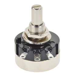
A potentiometer is basically a resistor with three pins, where the distance between two pins (side pins) can be changed, thereby changing the resistance value. The third pin (center tap) is connected to the resistor body, and a voltage proportional to the resistance between the two side pins can be read. Therefore, the potentiometer can be used to control the level of voltage or current, as well as provide an adjustable resistance value in the circuit.Working Principle of Potentiometer
The working principle of the potentiometer is based on its physical structure - a slidable contact point (wiper) that moves on the resistor body, thereby changing the impedance in the circuit. When the contact point moves on the resistor body, it changes the resistance value between the two fixed pins. Since the potentiometer is usually connected in series with a fixed resistor, the current flowing through the potentiometer changes accordingly when the contact point moves, which allows for fine control of the current or voltage in the circuit.What is the ?
There are two symbol representations for potentiometers: international standard and American standard. Although the international standard symbol is a more recent introduction, the American standard symbol is still popular in many reference materials.Potentiometer symbol (international standard):
According to the international standard, the potentiometer symbol is a rectangular box with two terminals on either side and an arrow in the middle.
Potentiometer symbol (American standard):
In the American standard, the potentiometer symbol features a sawtooth line similar to the resistor symbol, accompanied by an arrow above it.

Potentiometer symbol differences
Potentiometer symbols may vary in different applications and standards, but their basic principles and composition are the same. Generally, the symbol for a potentiometer consists of three parts: two terminals (usually represented as straight lines) and a middle contact that slides along the resistor body during adjustment. Here are some common differences in potentiometer symbols:1. Linear Potentiometer Symbol: For a linear potentiometer, the symbol is usually shown as a straight line with a movable contact in the middle, indicating that the resistance value increases or decreases linearly as the adjuster is moved.
2. Exponential Potentiometer Symbol: The symbol of an exponential potentiometer is similar to that of a linear one, but the contact in the middle may be marked as a curved line, indicating that the resistance value changes exponentially as the adjuster is moved.
3. Logarithmic Potentiometer Symbol: The symbol of a logarithmic potentiometer is also similar to that of a linear one, and the contact in the middle may be marked as a line with a specific angle, indicating that the resistance value changes logarithmically as the adjuster is moved.
4. Multi-Turn Potentiometer Symbol: For a multi-turn potentiometer (commonly used in precision instruments), the symbol may be similar to that of a single-turn potentiometer, but there will be an additional mark next to the contact, indicating that it can be rotated multiple times for finer adjustment.
5. Potentiometer Symbol with Switch: The symbol of a potentiometer with a switch usually has a switch symbol next to the potentiometer graphic, indicating that the potentiometer has a switch function.
6. Locking Potentiometer Symbol: The symbol of a locking potentiometer may be similar to that of a normal potentiometer, but there will be a lock icon next to the contacts, indicating that the potentiometer can be locked to prevent unintentional adjustment.
Different countries and regions may have their own standards and symbol systems. For example, the United States uses the IEEE standard and Europe uses the IEC standard. When reading technical literature, circuit diagrams, or electronic product manuals, you need to be aware that these symbols may vary depending on the standards followed. In actual use, the most important thing is to understand the characteristics and functions of the potentiometer represented by these symbols and make sure they are applicable to your circuit design.
Types of Potentiometers
Linear Potentiometer: The resistance of this potentiometer increases or decreases linearly as the sliding arm moves.Exponential Potentiometer: In this type of potentiometer, the resistance increases or decreases exponentially as the sliding arm moves, and is often used for volume control.
Digital Potentiometer: This is a potentiometer that adjusts the resistance value through digital control. It can be controlled by a microprocessor to provide more precise adjustment.
Potentiometer Application Fields
Potentiometers are widely used in various electronic products and electrical equipment. Some typical applications include:Volume control: In audio equipment, potentiometers are often used to adjust the volume of speakers or headphones.
Dimmer: In lighting applications, potentiometers can be used to adjust the brightness of light bulbs.
Sensors: In some sensors, such as position sensors or pressure sensors, potentiometers can be used to convert mechanical inputs into electrical signal outputs.
Test instruments: In multimeters and other test instruments, potentiometers are used to set the sensitivity or reference voltage of the measurement.
Motor control: In motor drive circuits, potentiometers can be used to control the speed and direction of the motor.
How to improve the adjustment accuracy of the potentiometer in the circuit?
1. Choose a high-quality potentiometer:Using a potentiometer with high precision and good temperature coefficient can significantly improve the adjustment accuracy.
2. Calibration:
Calibrate the potentiometer regularly to ensure that it remains within the specified accuracy range. Calibration can be performed using a standard resistance box or other calibration equipment.
3. Temperature control:
Since temperature changes affect the resistance of the potentiometer, maintaining a stable temperature environment or using a potentiometer with excellent temperature stability characteristics can help improve accuracy.
4. Reduce external interference:
Ensure that the potentiometer is not affected by mechanical vibration, electromagnetic interference, or other external factors, which may cause a decrease in accuracy.
5. Circuit design:
When designing the circuit, reasonable layout and optimized routing can help reduce noise and improve the performance of the overall circuit.
6. Use filters:
Adding appropriate filtering circuits, such as RC filters, to the input and output of the potentiometer can reduce noise and interference.
7. Software correction:
If the potentiometer is interfaced with a digital control system, nonlinearity or other errors can be corrected by software algorithms, such as look-up tables or PID adjustments to improve accuracy.
8. Packaging and installation:
Ensure that the potentiometer is mounted firmly and there is no looseness or vibration, as these conditions may affect its mechanical properties and thus affect accuracy.
9. Maintenance:
Regularly check and maintain the potentiometer, clean or replace worn parts to keep it in optimal condition.
10. Use fixed resistor dividers:
In some cases, fixed resistor dividers can be used instead of potentiometers to improve the stability and accuracy of the circuit.
Combined with the above methods, the adjustment accuracy of the potentiometer in the circuit can be effectively improved. However, it should be noted that the implementation of any improvement measures should be based on a deep understanding of the existing system, otherwise it may lead to performance degradation or other problems.
How to choose the right potentiometer for my circuit design?
When choosing the right potentiometer for your circuit design, you need to consider the following factors:Use environment: Consider the environmental conditions in which the potentiometer will work, such as temperature, humidity, vibration, etc., which will affect the performance and life of the potentiometer.
Circuit requirements: Select the type of potentiometer (such as linear, exponential, logarithmic, etc.), as well as its accuracy and stability according to the specific needs of the circuit.
Resistance range: Determine the required resistance range, which depends on the current and voltage in the circuit. Choosing the right resistance value can avoid overloading or underloading the circuit.
Power handling capability: Calculate the power level of the required potentiometer based on the operating voltage and current in the circuit to ensure that it can safely handle the power in the circuit.
Adjustment method: According to the needs of the circuit, choose an appropriate adjustment method, such as rotary, sliding, etc.
Physical size: Consider the space limitations on the circuit board and choose a potentiometer of the right size.
Cost: According to the budget, choose a potentiometer with high cost performance.
Supplier and brand: Choose a reputable supplier and brand to ensure the quality and after-sales service of the potentiometer.
Certification and standards: If the circuit design needs to meet specific industrial or safety standards, then it is necessary to choose a potentiometer that meets these standards.
In actual operation, you may also need to refer to the circuit design manual, the data sheet and recommendations of the potentiometer supplier, and test the performance of different potentiometers in the circuit through simulation software. Finally, conducting actual prototype testing is also an important step to verify whether the potentiometer is suitable for your circuit design.
Conclusion
As an indispensable part of electronic and electrical engineering, potentiometers provide a simple and effective means to adjust the current and voltage in the circuit. With the continuous development of electronic technology, potentiometers are also constantly evolving to meet the growing demand for precision control. Whether it is a simple volume adjustment or a complex position sensing, potentiometers play an irreplaceable role.
Statement
All articles (images, texts, audio) on this site are uploaded and shared by users, or integrated from relevant internet sources, only for user's learning. If your rights are violated, please contact the administrator to delete! Link to this article: https://www.jinftry.com

