Ring Counter: Working Principle, Truth Table, Diagram

What is a Ring Counter?
A ring counter is a type of sequential logic circuit that is commonly used in digital systems. It consists of a series of flip-flops connected in a circular fashion, where the output of one flip-flop is the input of the next, and the last flip-flop's output is fed back to the first flip-flop's input. This circulating pattern makes ring counters ideal for certain types of counting and sequencing applications. Ring counters are used in various applications, such as frequency division, digital clocks, and shift registers.
What is the Working Principle of Ring Counter?
The working principle of a ring counter is based on a series of D flip-flops. In a 4-bit ring counter, four flip-flops are connected in a loop. The output of one flip-flop is connected to the input of the next. The last flip-flop's output is connected to the input of the first. When the ring counter is initialized, only one flip-flop is set to '1', and the others are '0'. With each clock pulse, the '1' moves to the next flip-flop. This creates a repeating cycle of states.
Block Diagram of Ring Counter
To understand the structure better, let’s look at the block diagram of a 4-bit ring counter:
Flip-Flops: Four D flip-flops are used.
Clock Input: A common clock signal synchronizes all flip-flops.
Reset Input: Initializes the counter, setting the first flip-flop to '1' and the rest to '0'.
Here is a simplified block diagram:
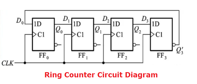
The diagram illustrates that the clock pulse (CLK) is distributed to all flip-flops at the same time, making it a Synchronous Counter.
Ring Counter Truth Table
The truth table shows the states of the flip-flops over time. Here’s an example for a 4-bit ring counter:
|
Clock Pulse |
D1 |
D2 |
D3 |
D4 |
|
0 |
1 |
0 |
0 |
0 |
|
1 |
0 |
1 |
0 |
0 |
|
2 |
0 |
0 |
1 |
0 |
|
3 |
0 |
0 |
0 |
1 |
|
4 |
1 |
0 |
0 |
0 |
How Many Types of Ring Counter?
The ring counter is a special kind of counter that operates in a loop. And it has several types in the electronic industry.
1. Straight Ring Counter (Simple Ring Counter)
A straight ring counter, also known as a simple ring counter, is the most basic form of ring counter. It consists of a series of D flip-flops connected in a circular chain. The '1' bit shifts from one flip-flop to the next with each clock pulse. If a four-bit straight ring counter is considered, it would cycle through four states.
State 1: 1000
State 2: 0100
State 3: 0010
State 4: 0001
2. Twisted Ring Counter (Johnson Counter)
A twisted ring counter, also known as a Johnson counter or switch-tail ring counter, is a modified version of the straight ring counter. In a Johnson counter, the inverted output of the last flip-flop is fed back to the input of the first flip-flop. This configuration allows the counter to have twice as many states as the number of flip-flops. Let’s take example of a 4-bit Johnson Counter, its state will be:
State 1: 0000
State 2: 1000
State 3: 1100
State 4: 1110
State 5: 1111
State 6: 0111
State 7: 0011
State 8: 0001
3. Bidirectional Ring Counter
A bidirectional ring counter can count in both directions, either clockwise or counterclockwise. This type of counter requires additional control logic to determine the direction of counting. Depending on the direction signal, the '1' bit shifts either left or right with each clock pulse. For instance, it just like:
Clockwise: 1000 -> 0100 -> 0010 -> 0001
Counterclockwise: 1000 -> 0001 -> 0010 -> 0100
4. Binary Ring Counter
A binary ring counter, also known as a one-hot counter, is a special type of counter where only one flip-flop is '1' at any given time, and the rest are '0'. This counter is similar to the straight ring counter but is often used in applications requiring simple state machines or state encoding.
State 1: 0001
State 2: 0010
State 3: 0100
State 4: 1000
What are Advantages of Ring Counter?
Ring counters are widely used in digital electronics due to their simplicity and specific applications. However, like any other technology, they come with their own set of advantages and disadvantages.
Advantages of Ring Counter
- Simplicity of Design
- High Speed
- Reduced Decoding Logic
- Predictable Timing
Disadvantages of Ring Counter
- Limited Count Capacity
- Initial State Setup
- Power Consumption
- Application Specificity
What is the Difference Between Ring Counter and Johnson Counter?
Ring counters and Johnson counters are both types of shift registers used in digital electronics for counting and sequencing purposes. While they share some similarities, they also have distinct differences in their design and functionality.
Connection of Flip-Flops
In a simple ring counter, the output of the last flip-flop is directly connected to the input of the first flip-flop, creating a loop where a single '1' circulates through the flip-flops. In contrast, a Johnson counter feeds the inverted output of the last flip-flop back to the input of the first flip-flop, forming a unique feedback mechanism that alters the state sequence.
Number of States
A ring counter has a number of states equal to the number of flip-flops used; for example, a 4-bit ring counter has four distinct states. Conversely, a Johnson counter has twice the number of states as the number of flip-flops, so a 4-bit Johnson counter possesses eight unique states, offering more versatility in applications requiring more states.
Pattern of States
The state pattern of a ring counter consists of a single '1' circulating among '0's, producing a simple and predictable sequence such as `1000`, `0100`, `0010`, and `0001` for a 4-bit counter. On the other hand, a Johnson counter generates a more complex sequence where both '1's and '0's circulate, resulting in states like `0000`, `1000`, `1100`, `1110`, `1111`, `0111`, `0011`, and `0001` for a 4-bit counter.
Applications
Ring counters are ideal for applications needing a straightforward and predictable sequence of states, such as digital clocks, sequence generators, and light displays. Johnson counters are better suited for applications requiring a higher number of states and more complex sequences, including divide-by-N counters and digital lock circuits, due to their extended state range and feedback mechanism.
In addition, the design of ring counters is relatively simple and easy to understand, making them a good choice for basic counting tasks. In contrast, Johnson counters, with their inverted feedback design, are slightly more complex but provide more states and flexibility.
Johnson Counter Truth Table
|
Qa |
Qb |
Qc |
Qd |
|
0 |
0 |
0 |
0 |
|
1 |
0 |
0 |
0 |
|
1 |
1 |
0 |
0 |
|
1 |
1 |
1 |
0 |
|
1 |
1 |
1 |
1 |
|
0 |
1 |
1 |
1 |
|
0 |
0 |
1 |
1 |
|
0 |
0 |
0 |
1 |
|
Repeat |
|||
Verilog HDL Program for Ring Counter
To write a basic Verilog HDL program, let’s take an example to a program of 4-bit ring counter. You can follow these steps:
l Module Declaration
Start by declaring the module and defining the input and output ports. The inputs will include a clock signal (clk) and a reset signal (reset). The output will be a 4-bit register (q).
l Always Block
Use an always block that triggers on the positive edge of the clock or the positive edge of the reset signal.
l Reset Condition
Inside the always block, first check for the reset condition. If the reset signal is high, initialize the output register q to 4'b0001 (binary representation of 1).
l Clock Condition
If the reset signal is not high, on each positive edge of the clock, shift the bits of the register to the left and wrap the most significant bit to the least significant bit.
Here is the complete Verilog HDL code for a 4-bit ring counter explained in words:
module ring_counter (
input clk, // Clock input
input reset, // Reset input
output reg [3:0] q // 4-bit output register
);
always @(posedge clk or posedge reset) begin
if (reset)
q <= 4'b0001; // Initialize to 0001 on reset
else
q <= {q[2:0], q[3]}; // Shift left and wrap around
end
endmodule
This code defines a 4-bit ring counter that resets to 0001 and shifts the bits left with each clock pulse, creating a circulating pattern.
What is ORI in Ring Counter?
ORI in the context of ring counters typically refers to the "Output Ring Indicator." This indicator signifies the current output state of the ring counter. It's used in diagnostic and testing contexts to verify the correct operation of the counter.
The ORI shows which flip-flop is currently set to '1'. In a properly functioning ring counter, the ORI moves sequentially through each flip-flop. It can monitor the ORI helps ensure that the ring counter is cycling through its states as expected. Any deviation from the expected sequence can indicate a malfunction or error in the counter's design or operation.
How to Design a Ring Counter?
Designing a ring counter involves creating a sequential circuit using flip-flops that circulates a single '1' or '0' bit through the flip-flops with each clock pulse. You can follow below steps to designing a simple 4-bit ring counter using D flip-flops.
Tools preparation
D Flip-Flops (4 for a 4-bit counter)
Clock Signal Source
Reset Signal (optional but recommended for initialization)
Logic Gates (if necessary for specific features)
Step-by-Step Design Process
1. Determine the Number of Flip-Flops
The number of flip-flops determines the number of states in the ring counter. For this example, we will design a 4-bit ring counter, so we need 4 D flip-flops.
2. Configure the D Flip-Flops
Each D flip-flop in the ring counter should be connected in a circular fashion. The output of one flip-flop becomes the input of the next flip-flop.
The output of the last flip-flop should be connected back to the input of the first flip-flop.
Each flip-flop should be driven by the same clock signal.
3. Initialize the Ring Counter
To start the ring counter in the correct state, you need to initialize it such that only one flip-flop is set to '1' and the others are '0'. This can be done using a reset signal or manually setting the initial states.
4. Connect the Flip-Flops
Flip-Flop 1 (FF1):
D input connected to the Q output of Flip-Flop 4 (FF4).
Clock input connected to the common clock signal.
Flip-Flop 2 (FF2):
D input connected to the Q output of Flip-Flop 1 (FF1).
Clock input connected to the common clock signal.
Flip-Flop 3 (FF3):
D input connected to the Q output of Flip-Flop 2 (FF2).
Clock input connected to the common clock signal.
Flip-Flop 4 (FF4):
D input connected to the Q output of Flip-Flop 3 (FF3).
Clock input connected to the common clock signal.
5. Verify the Counter Operation
Once the flip-flops are connected and initialized, apply the clock signal and observe the outputs. The '1' bit should circulate through the flip-flops with each clock pulse.
Is Ring Counter Asynchronous or Synchronous?
Ring counters are synchronous. In a synchronous counter, all the flip-flops are driven by a common clock signal. This means that all the flip-flops receive the clock pulse simultaneously, ensuring that they change state at the same time.
Synchronous counters, like ring counters, offer advantages in terms of timing and coordination. They avoid the propagation delays that can occur in asynchronous (ripple) counters, where the clock signal propagates through each flip-flop sequentially, causing a delay in state transitions.
In summary, ring counters are an integral part of digital systems, providing simple and predictable counting and sequencing capabilities. Their synchronous nature, combined with straightforward design and operation, makes them ideal for various applications, from sequence generation to state indication.
FAQs
Can a ring counter be used in a binary system?
No, ring counters are not binary counters. They follow a specific sequence of states.
What are typical applications of ring counters?
They are used in sequence generators, digital clocks, and rotating light displays.
How do you initialize a ring counter?
Use a reset signal to set the first flip-flop to '1' and others to '0'.
What is the main limitation of a ring counter?
Limited number of states, equal to the number of flip-flops used.
How does a Johnson counter differ in
terms of state count?
A Johnson counter has twice the number of states compared to a simple ring counter.
Statement
All articles (images, texts, audio) on this site are uploaded and shared by users, or integrated from relevant internet sources, only for user's learning. If your rights are violated, please contact the administrator to delete! Link to this article: https://www.jinftry.com

