What are the differences between synchronous and asynchronous counter?

What is a Synchronous Counter?
A synchronous counter is a type of digital counter where all the flip-flops (memory elements) are driven by a common clock signal. This ensures that all flip-flops in the counter change their state at the same instant when the clock pulse occurs. Synchronous counters are also known as parallel counters due to this simultaneous state change, which provides higher precision and speed in counting operations.
Synchronous counters can be designed using different types of flip-flops, such as JK flip-flops, D flip-flops, or T flip-flops. The choice of flip-flop type can impact the complexity and performance of the counter. In a synchronous counter, additional logic gates may be used to control the state transitions based on the current count and desired counting sequence.
Synchronous Counter Diagram
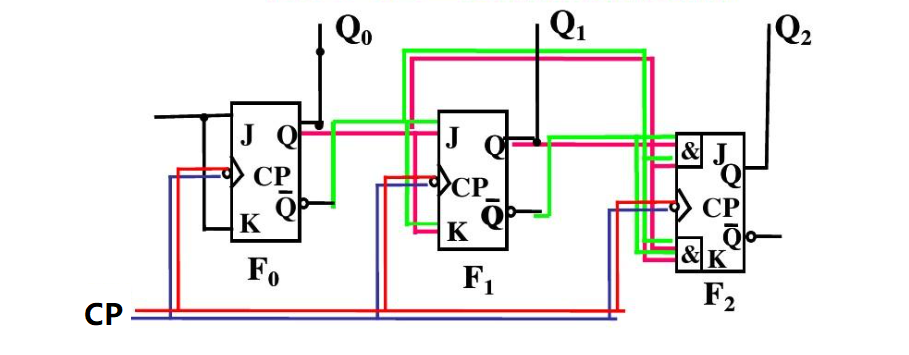
Here’s a typical diagram of a 3-bit synchronous counter:

Each flip-flop is connected to the same clock signal, ensuring that the state changes happen at the same instant. This design eliminates delays and ensures that the count progresses in perfect synchrony with the clock pulses.
What is an Asynchronous Counter?
An asynchronous counter, also known as a ripple counter, operates differently. In this type of counter, the first flip-flop is driven by the clock signal, and each subsequent flip-flop is driven by the output of the preceding flip-flop. This sequential clocking introduces a ripple effect, causing slight delays in state changes as the count progresses through the flip-flops.

Asynchronous counters are simpler in design compared to synchronous counters. They do not require complex additional logic circuits for their operation. However, the ripple effect can cause significant delays in large counters, making them unsuitable for high-speed applications. The design of asynchronous counters can be further simplified by using T flip-flops, which toggle their state with each clock pulse.
Asynchronous Counter Circuit Diagram
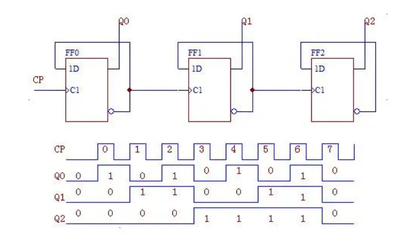
Here’s a basic representation of a 3-bit asynchronous counter:

In this arrangement, FF1's clock is triggered by FF0's output, and FF2's clock is triggered by FF1's output. This cascading effect means that each flip-flop changes state slightly later than the one before it, creating a ripple through the counter.
Asynchronous Up Counter
An asynchronous up counter counts in an ascending sequence. For example, a 3-bit asynchronous up counter will count from 0 to 7. Each time the clock pulse occurs, the first flip-flop toggles its state, and the ripple effect causes the subsequent flip-flops to toggle in sequence.
An asynchronous up counter can be used in applications where the counting sequence is not critical and where the delays introduced by the ripple effect are acceptable. For example, they are often used in simple digital clocks and event counters where high precision is not required.
Asynchronous Down Counter
Conversely, an asynchronous down counter counts in a descending order. It starts from the highest count (in the case of a 3-bit counter, this would be 7) and decrements to zero. The delay pattern is similar to the up counter but in reverse order, as the count decreases with each clock pulse.
Asynchronous down counters can be used in applications where a countdown sequence is required. They are commonly used in timers and countdown devices where the exact timing of the count is less critical.
Key Differences Between Synchronous and Asynchronous Counters
|
Item |
Synchronous Counters |
Asynchronous Counters |
|
Clocking Mechanism |
All flip-flops are clocked simultaneously. |
Flip-flops are clocked sequentially (ripple effect).
|
|
Speed |
Faster due to simultaneous state changes. |
Slower due to ripple delays. |
|
Design Complexity |
More complex, requires additional logic circuits. |
Simpler, fewer logic circuits needed. |
|
Glitch Susceptibility |
Less prone to glitches. |
More susceptible to glitches. |
|
Scalability |
Easier to scale, handles larger bit widths well. |
Harder to scale, cumulative delays limit bit width. |
|
Power Consumption and Heat |
Generally higher power consumption and heat. |
Lower power consumption and heat. |
|
Application Suitability |
High-speed, high-precision applications. |
Simpler, low-speed applications. |
|
Examples of Use |
Digital clocks, microprocessors, complex systems. |
Basic event counters, simple digital clocks. |
|
Propagation Delay |
Minimal, since all flip-flops change state simultaneously. |
Significant, due to the ripple effect causing cumulative delays.
|
|
Setup and Hold Time Requirements |
Requires careful consideration of setup and hold times to ensure reliable operation. |
Easier to meet setup and hold time requirements due to sequential state changes. |
|
Transition Detection |
Easier to detect transitions and generate specific outputs based on count value. |
More difficult to detect specific transitions due to staggered state changes. |
|
Testing and Debugging |
Can be more challenging to test and debug due to complexity and simultaneous state changes. |
Easier to test and debug due to simpler design and sequential state changes. |
|
Noise Immunity |
Better noise immunity due to simultaneous state changes and reduced susceptibility to glitches. |
More susceptible to noise and glitches due to ripple effect and sequential state changes. |
|
Power-On Behavior |
More predictable power-on behavior, easier to design for known initial states. |
Less predictable power-on behavior, may require additional circuitry to ensure known initial states. |
What are the Advantages of Using Synchronous Counters Over Asynchronous Counters?
Synchronous counters offer several advantages over asynchronous counters:
Precise Timing
All flip-flops switch states at the same time. This precision is critical in applications where timing is everything, like digital clocks or data processing circuits.
Higher Speed
Since there’s no delay between state changes, synchronous counters can operate at higher speeds. This makes them ideal for high-frequency applications, like certain types of processors and high-speed digital systems.
Reduced Glitches
With synchronous counters, you’re less likely to encounter glitches. Why? Because all flip-flops change state together, minimizing the chances of errors creeping in.
Scalability
Need to handle larger bit widths? No problem. Synchronous counters scale up more gracefully, making them versatile for more complex tasks.
In contrast, asynchronous counters, with their ripple effect, might stumble over their own feet if you try to push them too hard. They’re simpler and have their place, but for high-speed, precision tasks, synchronous counters are usually the way to go.
What Applications are Best Suited for Asynchronous Counters?
Asynchronous counters, despite their limitations in speed and precision compared to synchronous counters, are well-suited for a variety of applications where these factors are less critical. Their simplicity and ease of design make them advantageous for several practical uses:
1. Simple Event Counting
Asynchronous counters are ideal for simple event counting applications where high-speed operation is not necessary. They are used to count occurrences such as products on a production line or people entering a room. For example, in a turnstile system at a theme park, an asynchronous counter can track the number of visitors entering through each gate, providing a simple and effective way to monitor attendance.
2. Frequency Division
Asynchronous counters are effective for frequency division tasks, which involve dividing the frequency of an input clock signal to produce a lower frequency output. This is useful in devices like digital clocks and timing circuits. For instance, a digital wristwatch might use an asynchronous counter to convert the high-frequency signal from a quartz crystal into the lower frequency needed to drive the time display.
3. Low-Speed Digital Clocks
In low-speed digital clock applications, the ripple delay of asynchronous counters is negligible, making them suitable for generating time intervals in basic devices. An example would be a kitchen timer that uses an asynchronous counter to measure cooking durations, where precise timing is less critical but simplicity and cost-effectiveness are important.
4. Basic Timers and Delays
Asynchronous counters are suitable for creating basic timing and delay circuits where precise timing is not essential. They are used in applications such as simple electronic alarm clocks and timers. For instance, an asynchronous counter can be used in a basic alarm clock to generate the delay needed to activate the alarm sound after a set period.
5. Low-Speed Control Systems
In low-speed control systems where exact timing is less crucial, asynchronous counters can be used effectively. For example, in a basic irrigation control system, an asynchronous counter can help manage the timing intervals for watering cycles, ensuring plants receive water at regular, but not necessarily precise, intervals.
Asynchronous counters are also great for educational purposes. They’re simpler to design and understand, making them perfect for teaching the basics of digital electronics and counter design. So, while they might not win any speed contests, they have a comfortable niche in the world of digital circuits.
How Can You Implement a 3-Bit Asynchronous Up Counter?
Implementing a 3-bit asynchronous up counter involves connecting three JK flip-flops in series, with each flip-flop representing one bit of the counter. The counter will count from 0 to 7 (000 to 111 in binary) in an upward sequence. Here's a detailed step-by-step guide on how to implement it:
Gather Your Components: You’ll need to prepare three JK flip-flops. JK flip-flops are handy because they toggle their state with each clock pulse when both J and K inputs are set to 1. In addition, clock signal generator, power supply and connecting wires are needed as well.
Step-by-step guide to connect a 3-bit synchronous up counter
Step 1: Understanding the JK Flip-Flop
A JK flip-flop has three main inputs: J, K, and Clock (CLK). It also has two outputs: Q (normal output) and Q' (complementary output). The behavior of the JK flip-flop is as follows:
1. When J = 0 and K = 0, there is no change in the output.
2. When J = 0 and K = 1, the output resets to 0.
3. When J = 1 and K = 0, the output sets to 1.
4. When J = 1 and K = 1, the output toggles (i.e., changes from 0 to 1 or from 1 to 0).
Step 2: Connecting the Flip-Flops
1. First Flip-Flop (FF1):
l Connect the clock signal to the CLK input of FF1.
l Connect J and K inputs of FF1 to logic high (1), ensuring that FF1 will toggle with each clock pulse.
2. Second Flip-Flop (FF2):
l Connect the Q output of FF1 to the CLK input of FF2. This means FF2 will toggle on the falling edge of FF1's output.
l Connect J and K inputs of FF2 to logic high (1), ensuring that FF2 will toggle when triggered by FF1.
3. Third Flip-Flop (FF3):
l Connect the Q output of FF2 to the CLK input of FF3. This means FF3 will toggle on the falling edge of FF2's output.
l Connect J and K inputs of FF3 to logic high (1), ensuring that FF3 will toggle when triggered by FF2.
Step 3: Power Supply and Ground Connections
l Connect the power supply (Vcc) to the Vcc pin of each flip-flop.
l Connect the ground (GND) to the ground pin of each flip-flop.
Step 4: Output Connections
l The Q outputs of FF1, FF2, and FF3 represent the 3-bit binary output of the counter.
l Connect the Q outputs to LEDs or other display devices to visualize the count.
Step 5: Clock Signal
Apply a continuous clock signal to the CLK input of FF1. This can be generated using a clock pulse generator or a simple oscillator circuit.
Step 6: Operation
Connect the output of each flip-flop to the clock input of the next flip-flop. And the output of each flip-flop represents a bit in the 3-bit binary count.
This cycle repeats, counting from 000 to 111 and then resetting to 000, creating a 3-bit asynchronous up counter.
Table for 3-Bit Asynchronous Up Counter
|
Clock Pulse |
FF3 (Q2) |
FF2 (Q1) |
FF1 (Q0) |
Binary Count |
Decimal Count |
|
Initial State |
0 |
0 |
0 |
000 |
0 |
|
1 |
0 |
0 |
1 |
001 |
1 |
|
2 |
0 |
1 |
0 |
010 |
1 |
|
3 |
0 |
1 |
1 |
011 |
3 |
|
4 |
1 |
0 |
0 |
100 |
4 |
|
5 |
1 |
0 |
1 |
101 |
5 |
|
6 |
1 |
1 |
0 |
110 |
6 |
|
7 |
1 |
1 |
1 |
111 |
7 |
|
8 |
0 |
0 |
0 |
000 |
0 |
This table shows how the 3-bit asynchronous up counter progresses through its states with each clock pulse.
Table for 3-Bit Asynchronous Down Counter
A 3-bit asynchronous down counter counts down from 7 to 0 in binary with each clock pulse. Here is the table showing the state transitions:
|
Clock Pulse |
FF3 (Q2) |
FF2 (Q1) |
FF1 (Q0) |
Binary Count |
Decimal Count |
|
Initial State |
1 |
1 |
1 |
111 |
7 |
|
1 |
1 |
1 |
0 |
110 |
6 |
|
2 |
1 |
0 |
1 |
101 |
5 |
|
3 |
1 |
0 |
0 |
100 |
4 |
|
4 |
0 |
1 |
1 |
011 |
3 |
|
5 |
0 |
1 |
0 |
010 |
2 |
|
6 |
0 |
0 |
1 |
001 |
1 |
|
7 |
0 |
0 |
0 |
000 |
0 |
|
8 |
1 |
1 |
1 |
111 |
7 |
This table illustrates how the 3-bit asynchronous down counter progresses through its states with each clock pulse, counting down from 7 to 0. Here is an explanation of each item.
l Initial State (111): All flip-flops are initially set.
l Clock Pulse 1: FF1 toggles from 1 to 0, making the count 110 (6 in decimal).
l Clock Pulse 2: FF1 toggles from 0 to 1, causing FF2 to toggle from 1 to 0, resulting in 101 (5 in decimal).
l Clock Pulse 3: FF1 toggles from 1 to 0, making the count 100 (4 in decimal).
l Clock Pulse 4: FF1 toggles from 0 to 1, causing FF2 to toggle from 0 to 1, and FF3 toggles from 1 to 0, resulting in 011 (3 in decimal).
l Clock Pulse 5: FF1 toggles from 1 to 0, making the count 010 (2 in decimal).
l Clock Pulse 6: FF1 toggles from 0 to 1, causing FF2 to toggle from 1 to 0, resulting in 001 (1 in decimal).
l Clock Pulse 7: FF1 toggles from 1 to 0, resetting the count to 000 (0 in decimal).
l Clock Pulse 8: FF1 toggles from 0 to 1, causing FF2 to toggle from 0 to 1, and FF3 toggles from 0 to 1, returning to the initial state 111 (7 in decimal).
FAQs
Q1: Can I use an asynchronous counter for high-frequency applications?
A1: It is not recommended due to the ripple effect causing timing delays. Synchronous counters are better suited for high-frequency applications.
Q2: How do I decide between a synchronous and an asynchronous counter?
A2: If precise timing and speed are critical, choose a synchronous counter. For simpler, low-speed applications, an asynchronous counter is sufficient.
Q3: What is a mod-10 counter?
A3: A mod-10 counter, also known as a decade counter, counts from 0 to 9 before resetting to 0. It can be synchronous or asynchronous.
Q4: How does the ripple effect impact asynchronous counters?
A4: The ripple effect introduces a delay as the state change propagates through each flip-flop, making asynchronous counters slower.
Q5: Can I convert an asynchronous counter to a synchronous one?
A5: It is possible, but it requires redesigning the circuit to ensure all flip-flops receive the clock pulse simultaneously.
Statement
All articles (images, texts, audio) on this site are uploaded and shared by users, or integrated from relevant internet sources, only for user's learning. If your rights are violated, please contact the administrator to delete! Link to this article: https://www.jinftry.com


