RG2012N-57R6-W-T5 Product Introduction:
Susumu Part Number RG2012N-57R6-W-T5(Chip Resistor - Surface Mount), developed and manufactured by Susumu, distributed globally by Jinftry. We distribute various electronic components from world-renowned brands and provide one-stop services, making us a trusted global electronic component distributor.
RG2012N-57R6-W-T5 is one of the part numbers distributed by Jinftry, and you can learn about its specifications/configurations, package/case, Datasheet, and other information here. Electronic components are affected by supply and demand, and prices fluctuate frequently. If you have a demand, please do not hesitate to send us an RFQ or email us immediately sales@jinftry.com Please inquire about the real-time unit price, Data Code, Lead time, payment terms, and any other information you would like to know. We will do our best to provide you with a quotation and reply as soon as possible.
Chip resistance-surface Mount (Chip resistance-surface mount) Surface Mount is an electronic component assembly technology in which the Resistor and other components are directly pasted to the surface of the printed circuit board. There is no need to reserve the pupil for the original, and the electrical connection is realized by brazing, which greatly improves the integration and processing speed of the circuit board. In the circuit, the chip resistor can not only stabilize the current and voltage, prevent excessive current or voltage from causing damage to the chip, but also carry out impedance matching in signal transmission to ensure that the signal is smooth and without loss. In addition, the chip resistance can also filter out the interference signal, improve the anti-interference ability of the system, and ensure the stability and reliability of the circuit. Surface mounting of chip resistance can greatly improve the efficiency of chip resistance.
Application
Chip resistance-surface Mount has a wide range of applications, It is widely used in communication equipment (such as mobile phones, TV sets), computer equipment (motherboard, graphics card), automotive electronics (engine control unit, braking system), industrial control (PLC, sensor) and medical equipment (electrocardiograph, blood pressure monitor) and other fields. Its compact size and high-precision characteristics enable electronic equipment to be further miniaturized and refined to meet the diversified needs of modern science and technology.
FAQ about Chip Resistor - Surface Mount
-
1. What is a Chip Resistor?
Chip Resistor, also known as chip fixed resistors, are resistors designed for surface mounting. They can be mounted directly to the surface of a printed circuit board (PCB) without drilling holes like traditional through-hole components.
Such resistors are usually much smaller than traditional resistors, so they take up much less space on the circuit board. The use of SMD resistors is due to the invention of surface mount technology (SMT), which not only reduces the size of components, but also greatly reduces the time to manufacture circuits. SMD resistors are mainly used in professionally manufactured PCBs, while through-hole resistors are more commonly used in most homemade circuits because they are more convenient to install and do not require specialized equipment.
There are many ways to express the resistance value of SMD resistors, including direct marking, three-digit digital representation, four-digit digital representation, EIAJ code representation, etc. These methods enable the resistance value of the resistor to be clearly marked on the resistor for easy identification and use. In addition, SMD resistors are also resistant to moisture and high temperatures, and have a small temperature coefficient, which allows them to maintain good performance in various environments.
-
2. How to choose Chip Resistor?
The application of surface mount technology (SMT) has been very common, and the proportion of electronic products assembled by SMT has exceeded 90%. my country began to introduce SMT technology in the 1980s. With the development of small SMT production equipment, the application scope of SMT is further expanding. Aviation, aerospace, instrumentation, machine tools and other fields are also using SMT to produce various small-volume electronic products or components.
In recent years, in addition to electronic product developers using SMT devices to develop new products, maintenance personnel have also begun to repair electronic products assembled by SMT technology in large quantities.
The models of SMT resistors are not uniform, and are set by each manufacturer, and the models are particularly long (consisting of more than a dozen English letters and numbers). If you can correctly propose various parameters and specifications of SMT resistors when purchasing, you can easily purchase (or order) the required resistors.
There are 5 parameters for SMT resistors, namely size, resistance, tolerance, temperature coefficient and packaging.
1. Size series SMT resistor series generally have 7 sizes, represented by two size codes. One size code is a 4-digit EIA (Electronics Industry Association) code, the first two digits and the last two digits represent the length and width of the resistor, in inches. The other is a metric code, also represented by 4 digits, in millimeters. Resistors of different sizes have different power ratings. Table 1 lists the codes and power ratings of these seven resistor sizes.
2. Resistance series The nominal resistance is determined by series. Each series is divided by the tolerance of the resistor (the smaller the tolerance, the more resistance divisions), among which the most commonly used is E-24 (the tolerance of the resistance value is ±5%), as shown in Table 2.
The resistance value is indicated by three digits on the surface of the chip resistor, of which the first and second digits are valid numbers, and the third digit indicates the number of zeros. When there is a decimal point, it is indicated by "R" and occupies one valid digit. The nominal resistance code representation method is shown in Table 3.
3. Tolerance The tolerance of chip resistors (carbon film resistors) has 4 levels, namely F level, ±1%; G level, ±2%; J level, ±5%; K level, ±10%.
4. Temperature coefficient The temperature coefficient of chip resistors has 2 levels, namely W level, ±200ppm/℃; X level, ±100ppm/℃. Only resistors with tolerance level F use level x, and resistors with tolerance levels of other levels are generally level w.
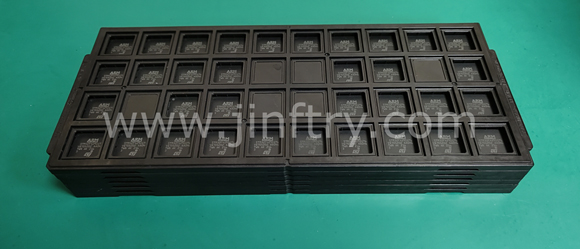
5. There are two main types of packaging: bulk and tape and roll.
The operating temperature range of chip resistors is -55--+125℃, and the maximum operating voltage is related to the size: 0201 is the lowest, 0402 and 0603 are 50V, 0805 is 150V, and other sizes are 200V.
6. The numbers on the surface of the chip resistors are arranged horizontally, and are specified to be represented by three digits, of which the first two are valid digits, and the third is the exponent of 10, in units of ohms. For example: 473 means 47×103=47 kΩ. If the second character on the surface of the resistor used to indicate the resistance value is the letter R, it represents a decimal point, for example: 5R1 means the resistance value is 5.1Ω.
-
3. Chip Resistor package power relationship
Formula
Current = (rated power / resistance) square root
Power P = U2 / R
Package Rated power 70°C Maximum operating voltage (V) Imperial (inch) Metric (mm)
0201 0603 1/20W / 25
0402 1005 1/16W / 50
0603 1608 1/16W 1/10W 50
0805 2012 1/10W 1/8W 150
1206 3216 1/8W 1/4W 200
1210 3225 1/4W 1/3W 200
1812 4832 1/2W / 200
2010 5025 1/2W 3/4W 200
2512 6432 1W / 200

 Lead free / RoHS Compliant